
Subtractive technologies
Digital fabrication is made up of design and production processes that harness the potential of combining computer-aided design (CAD) and computer-aided manufacturing (CAM) software, with CNC (computer numeric control) machines. These can be divided into additive and subtractive fabrication technologies.
Subtractive fabrication
Subtractive fabrication is a generic term used to name various fabrication processes based on the use of CNC tools that allow digital designs to be materialized by removing material through cutting, drilling and grinding.

SUBTRACTIVE TECHNOLOGIES
Laser cutting, router CNC, EDM machining and water jet cutting.
LASER CUTTING
A laser cutter is a particular type of CNC machine. There are several types of laser cutters, but all of them cut and engrave various materials from a laser beam. It is one of the most common technologies to find in a digital fabrication lab, and you will find cutters of various sizes and powers.
Operation: Laser beam cutting.
Advantages: Great precision, definition and quality of finish. Relatively low cost.
Disadvantages: Can´t cut metal or glass. You can only process material in the X and Y axes.


ROUTER CNC
A Computer Numerical Control Router is a cutting machine; this equipment works by means of a milling cutter that roughs the material, executing programmed advance movements in three possible axes (X, Y, Z) making it possible to carry out cutting, drilling, engraving and 3D carving in different materials. According to the type and thickness of the material, cutters of different diameters are chosen, and the speed and power values of the cutter are configured.
Operation: Cut by milling machine.
Advantages: Great precision, definition and quality of finish. Relatively low cost. You can process the material in Z, so you can do low and high reliefs in addition to cutting.
Disadvantages: Cannot cut metal or glass.
EDM MACHINING
CNC cutting machine that processes the material from wire EDM, used to manufacture highly hard parts. A metallic wire receives electrical discharges that produce sparks, thus eliminating the material, which is removed with a constantly flowing dielectric fluid.
Operation: Cutting from wire EDM.


WATER JET CUTTING
Uses powerful water jets for hard materials. Combining high-pressure water streams at a precise angle and speed, mixed with an abrasive, the head processes the material into cuts.
Operation: Cutting by water jet.
Advantages: Allows cutting metals and stone.
LASER CUTTING
Specifications, considerations and general aspects
¿How does it work?
The laser beam is generated inside a tube from carbon dioxide with the mixture of other gases. The laser beam leaves the gas tube and is reflected by a mirror system until it reaches the nozzle. The material is located at a certain distance from this, and by means of movements in the X and Y axes the material is processed.

LASER CUTTING PARAMETERS
The focal length of a lens is the distance between the optical center of the lens and the focus. It is important to respect this distance so that the laser cuts the material optimally. This equipment can generate cuts and engravings in different materials. According to the type and thickness of the material, the speed and power values of the laser beam are configured, as well as the distance between the nozzle and the material. The laser cutter has the possibility of cutting, line engraving, folding engraving, kerfing, etc.

DIMENSIONS AND MATERIALS
The maximum cutting dimensions of the cutters available in the FabLab are:
- William Gibson: 1118mm in X and 890mm in Y, maximum thickness 6mm
- Ursula K Le Guin: 1200mm in X and 2400mm in Y. Maximum thickness 9mm.
The materials that can be manufactured on this equipment are: mdf, multi-laminate, different types of cardboard (grey, Swedish, corrugated, feather, etc.). Various polymers can also be worked (pet, acrylic, eva rubber, etc). This equipment cannot work with PVC.
FABRICATION STRATEGIES
There are many ways to design and manufacture objects from the use of digital manufacturing technologies such as the laser cutter.
One way is to start from three-dimensional virtual models and, based on unfolding or sectioning processes, break them down into pieces that will be cut using the laser cutter.
Another possibility is to design directly in two dimensions, using vector software.

TECHNIQUE BY FACES_ INSERTS

TECHNIQUE BY FACES_ PLICATE

SOLID SECTIONED TECHNIQUE

SECTIONED TECHNIQUE WITH INSERTS

Depending on the geometry of the piece, it is possible to section or divide it into as many parts as necessary to optimize printing, guarantee a good finish of the piece and avoid the excessive use of supports that later affect the surface aesthetics of the piece.
CONSIDERATIONS
Whatever the manufacturing strategy we have chosen, we must take into account the following considerations:
MATERIAL THICKNESS
Although the cutter only makes cuts in the X and Y axes, that is, in two dimensions, we are going to work with different materials that have different thicknesses. This must be considered when designing joints and inserts.
CUTTING LINE THICKNESS
Although it is considered that the thickness of the cutting line is negligible, in relation to other technologies, if we are working with models that require great precision, we must consider that the cutting line is actually approximately 0.2mm.
JOINTS TYPES

Flat edge joint
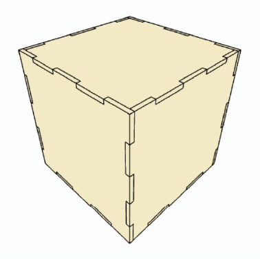
Finger joint
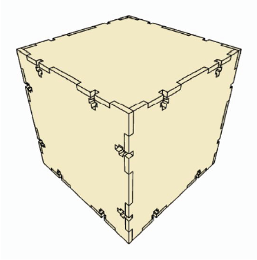
T-slot joint
INSERTS

ASSEMBLIES

KERFING AND ELASTIC INSERTS


MACHINING PROCESS
Subtractive technologies
The setting procedure for engraving/cutting is called “machining” and is done in the laboratory. To achieve a good result, the file that is taken to the laboratory must be carefully prepared, with the considerations detailed below:
- The files must be vector since the machining process does not recognize images. In other words, once your cutting file has been designed, you must export it as .dxf preferably or in .pdf, .svg or .cdr (Corel X4 version). Other types of files will not be accepted.
- In digital fabrication we always work on a 1:1 scale, and the units must be mm. When exporting the files, it is your responsibility to ensure that they are at the exact scale of the model.
- The format of the sheet configured in the program must match the size of the material to be used (A0, A1, etc.).
- Always dimension a part.
- To indicate the different types of cutting, they must be differentiated by color and the entire file must be worked exclusively with the CMYK color palette.
- Color reference: Engraving: magenta; Cut: cyan. In the case of needing more colors to prioritize the order of the cuts, or the different types of operations, any color from the CMYK palette can be taken and then indicated to the person in charge of the FabLab.
- Layout: leave a 10 mm edge margin around its entire perimeter.
- Avoid waste.
- The minimum distance between cutting lines must be equal to the thickness of the material to be worked.
- Verify that there are no overlapping lines (overkill or SelDup command)
- Verify that all lines are coplanar
- Do not work with hatches


DIE CUTTING SYSTEM
To prevent pieces smaller than 80x80mm from falling between the ribs of the laser cutter bed, it is necessary to implement a die-cutting system. This is accomplished by leaving the polylines open. The opening must be at least 1mm.

MACHINING SOFTWARES

COMMON MISTAKES
POINTS
NON-COPLANAR LINES
SUPERPOSITIONS

PROCEDURE FOR PROTOTYPING
Digital Fabrication Laboratory Operation – FabLab MVD
All people who want to make use of the laboratory in any of its modalities must schedule a day and time at least 72 hours in advance through the email labfab@fadu.edu.uy. The students will be able to use the laboratory for a maximum of 2 hours per month. The laboratory service for students will be subject to the availability of the FabLab, so it is advisable to coordinate this date as far in advance as possible.
The number of hours necessary to carry out the work must be taken into account, including the machining of the files and the cutting and engraving time.
To schedule the students must send the cut file by mail as soon as posible, and then they must present themselves personally with a copy of the Authorization Form signed by a teacher responsible for the subject or project on which they are going to work, and bring the material for the cut. The form is available at http://www.fadu.edu.uy/labfab. During the cutting, the student must remain in the laboratory.
In return for the use of the Laboratory, in the case of students, we request that the same amount of material to be used be left as a donation; so they must bring double the necessary material. In the case of teachers, the donation of supplies is requested to be previously agreed. It is convenient to bring a box or bag to remove the cut/engraved material.
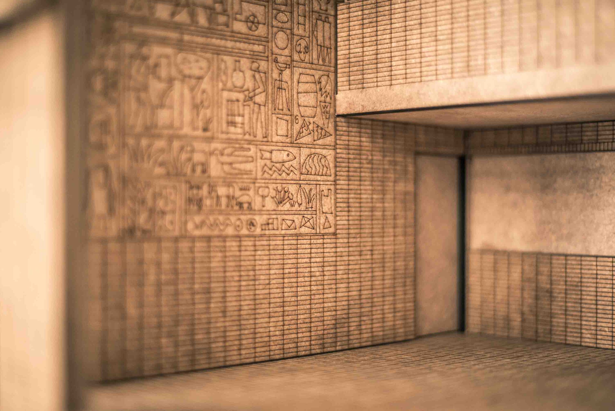
DIGITAL INTEGRATION CENTRE PROJECTS
Fabricated in subtractive technologies
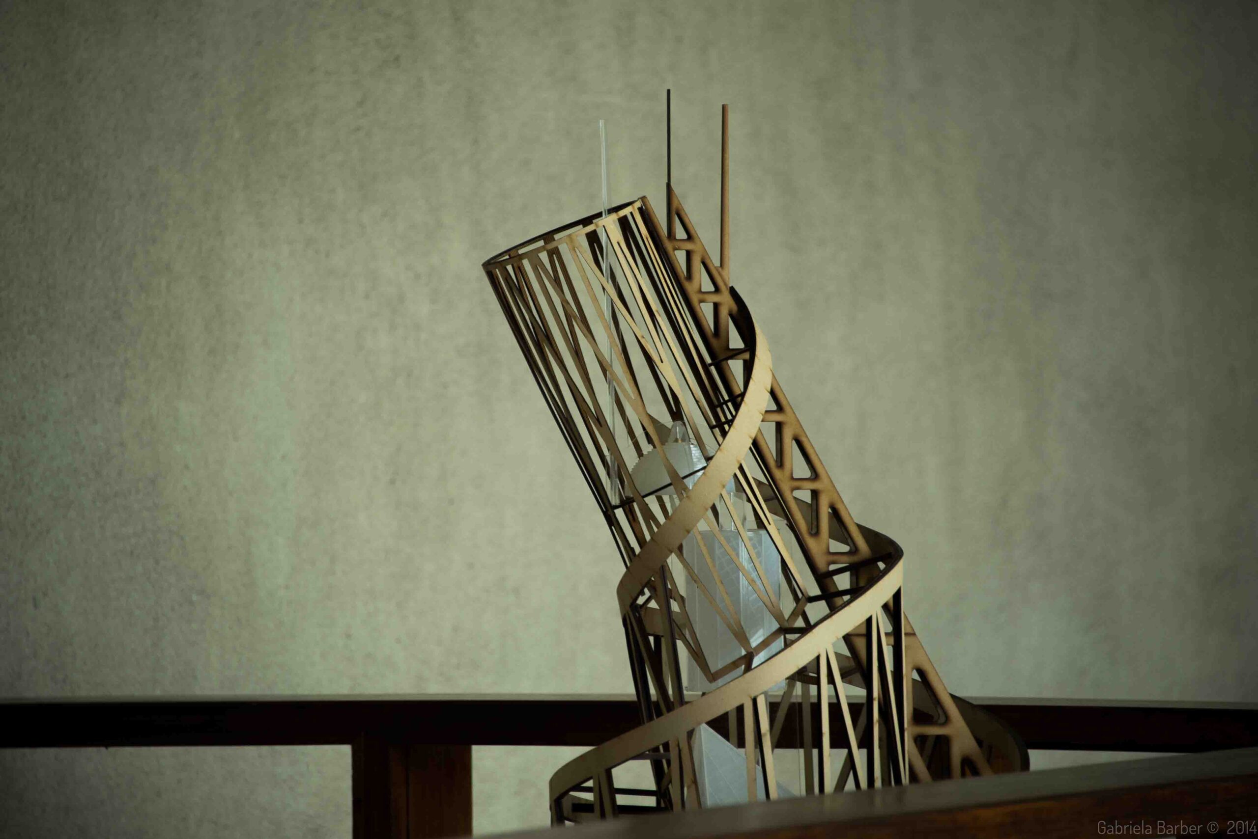
Uthopia, the unbuilt
Digital fabrication of unbuilt architectures
Studer
Exhibition: Obsesion; MPR+TTG
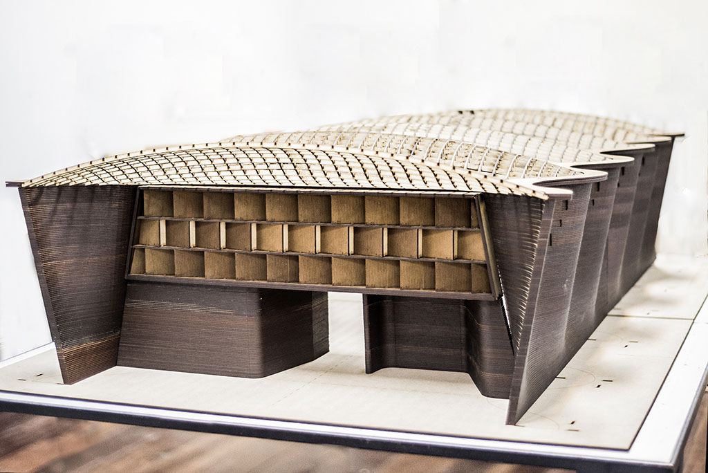
Dieste Ex Machina
Cristo Obrero church
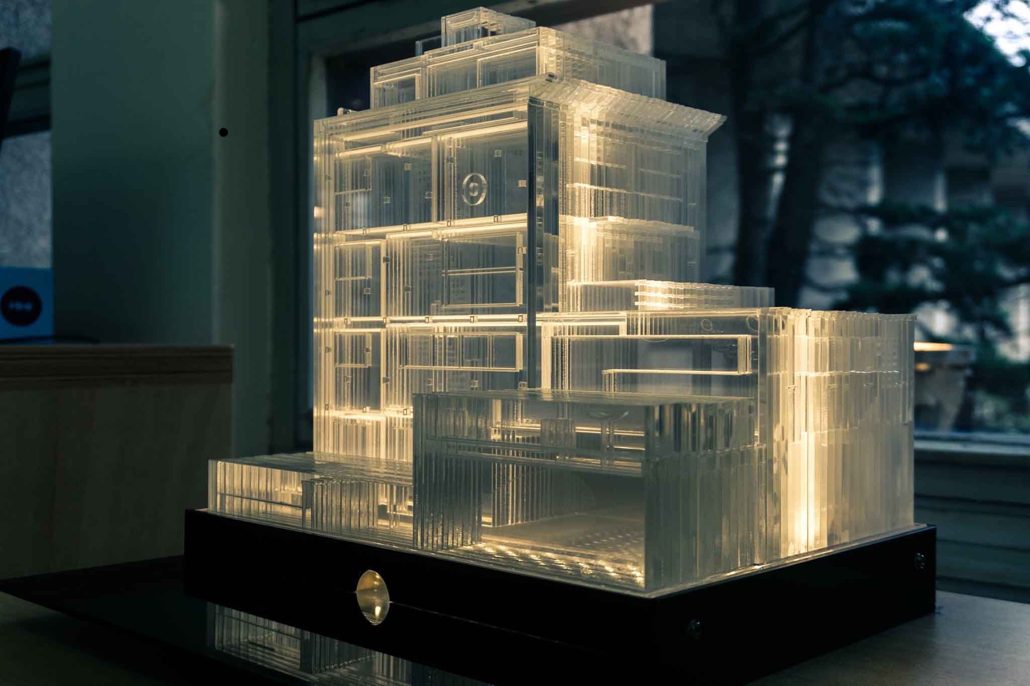
Architecture models
Laser cutting in acrilic material, Vilamajó house.